Which grid types are there?

In building installations, grid systems are important for the safety and efficiency of electrical systems. The different grid systems, TT, IT, TN-C, TN-C-S and TN-S systems, offer different approaches to earthing and residual current discharge. Each of these grid systems has specific applications as well as advantages and disadvantages that must be taken into account during planning and installation.

Structure of the grid

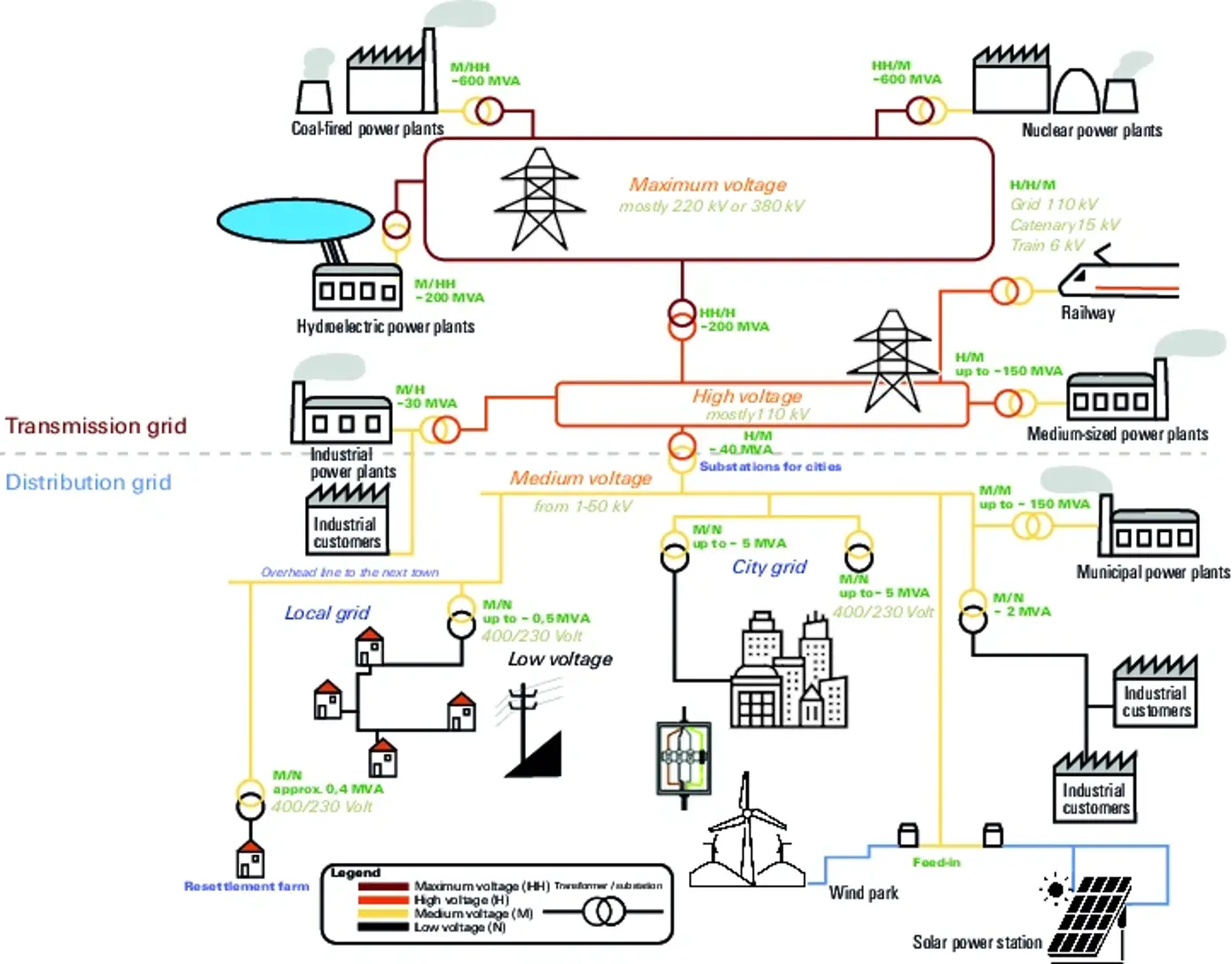
The grid is divided into a transmission grid and a distribution grid.

The transmission grid comprises the extra-high and high-voltage grids and the distribution grids are in the medium and low-voltage range.

The grid systems of the low-voltage distribution grid

The international standard IEC 60364 differentiate between three groups of earthing arrangements with the letter codes TN, TT and IT.

First letter


Second letter

Third letter

Earthing at current sourceEarth connections of the devicesUse of Neutral and PE
T
Direct earthing of current source (Star point)
T
Device direct earth, independent from the earthing and power device

C
Neutral and PE are combination with one wire
I
Insulated structure
N
Device is direct connected to standard earth
S
Neutral and PE are used separate

The TT system

TT mains system type

  • T: Direct earthing of current source (Star point)
  • T: Device direct earth, independent from the earthing and power device

TT mains system type

  • Hospitals (distribution group 1 e.g.: emergency room)
  • Industry (sensitive processes)

TT mains system type

  • Clear separation of Neutral and PE
  • EMC-compliant (no stray currents)
  • No extra potential equalisation
  • Simple planning and installation
  • Switch-off at the first error
  • Simple expansion of the installation

TT mains system type

  • Depending on earthing impedance
  • Use of RCD devices required
  • Potential differences between N and PE
  • with N-interruption = high voltage at the load

The IT system

IT mains system type

  • I: Insulated structure
  • T: Device direct earth, independent from the earthing and power device
  • The neutral is not always present in the IT Grids

IT mains system type

  • Hospitals (distribution group 2 e.g.: surgery room / Intensive care unit)
  • Industry (sensitive processes)

IT mains system type

  • Single-fault protection (galvanic isolation)
  • High level of personal safety
  • High level of fail-safety
  • EMC-compliant (no stray currents)
  • No switch-off at the first fault (hospitals, flight safety)

IT mains system type

  • Insulation monitoring required
  • Time-consuming search for the insulation fault
  • Limited to local areas (decentralised)
  • Cost-intensive

The TN-C system / classic earthing

TN-C mains system type

  • T: Direct earthing of current source (Star point)
  • N: Device is direct connected to standard earth
  • C: Neutral and PE are combination with one wire

  • i.e: Neutral and PE functions are combined in a single conductor, the PEN, throughout the entire grid sytem

TN-C mains system type

  • NS inventory grids (‘classic earthing’)
  • EVU-NS grids
  • Industry, residential buildings, public buildings...

TN-C mains system type

  • Simple planning and installation
  • Cost-efficient
  • Inventory protection
  • Switches off at the first fault; is used in electrical installations in which the receivers inherently have very high insulation faults (Radar equipment, etc.).

TN-C mains system type

  • Vagrant currents (not EMC-compliant)
  • No RCD protection possible
  • PEN interruption = housing voltage
  • Protective conductor potential
  • New construction no longer authorised
  • Installations must be very carefully calculated and tested with regard to overcurrent protection. Every change must be analysed.

The TN-C-S system / modern earthing

TN-C-S system

  • T: Direct earthing of current source (Star point)
  • N: Device is direct connected to standard earth
  • C: Neutral and PE are combination with one wire
  • S: Neutral and PE are used separate

  • i.e: Neutral, PEN and the potential equalisation system are connected once at the central earthing point (ZEP). From this point, a TN-C grid becomes a TN-S grid (TN-C-S grid).

TN-C-S system

  • NS existing grids (‘modern earthing’)
  • EVU-NS grids
  • Industry, residential buildings, public buildings...

TN-C-S system

  • Limited to ZEP environment
  • Best solution for multiple feed-in
  • EMC-compliant (with correct planning)

TN-C-S system

  • High planning requirements (out of the central earthing point)
  • High risk of meshing (stray currents)
  • High demands for plant engineers and installers
  • With N-interruption = high voltage at the load

The TN-S-System

TN-S-System

  • T: Direct earthing of current source (Star point)
  • N: Device is direct connected to Standard earth
  • S: Neutral and PE are used separate
  • i.e: Neutral and PE are present throughout the entire network as separate conductors.

TN-S-System

  • New distribution grids
  • Industry, residential buildings, public buildings, data centres...
  • Many industrialised countries

TN-S-System

  • Clear separation of Neutral and PE
  • EMC-compliant (no stray currents)
  • Increased personal safety thanks to RCD
  • Simple localisation of errors

TN-S-System

  • Consideration of upstream grid (planning)
  • Cost-intensive with multiple feed-in (Low-voltage main distribution board)
  • Cost-intensive/expensive for retrofitting
  • N-interruption = high voltage at the load

Mains voltages

Grid voltage is the electrical voltage provided by the energy suppliers in the electricity grids that is used to transmit electrical energy. In a narrower sense, grid voltage is often understood to be the level of alternating voltage in low-voltage grids.

Downloads

Consulting & Support

* Required fields